Welcome to BIM Technologies
  
Artcore
  • Home
  • Services
  • Products
    • Autodesk
    • Bentley
    • Request Free Trial
  • Training
    • Autodesk Training
    • Bentley Training
    • Tekla Training
    • MS Project Training
    • Primavera P6 Training
  • Upcoming
  • Recruitment
  • Contact us

Upcoming Events

[searchandfilter fields=",category,post_tag" headings=",Dates,Cities & Countries" hierarchical="1"]

Author: BIM TECHNOLOGIES

Complete Revit Course: Learn To Create Architectural Projects With Precision And Efficiency

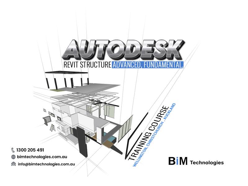
Master Revit Structure in Auckland, Wellington & Christchurch with our advanced & fundamental training courses. Plus, expert 3D Scan to BIM modeling services.

Complete Revit Course: Learn To Create Architectural Projects With Precision And Efficiency

If you are a student or professional in the field of architecture, civil engineering or interior design, you have certainly heard of Revit. This software is probably one of the most popular of its kind in the AEC industry. Used by architects and engineers throughout their projects, Revit has truly facilitated the work of professionals in the sector and covers all stages of design and construction, as well as across multiple disciplines.

After completing the Autodesk Revit structure advanced, fundamental, training course in Wellington, Christchurch, and Auckland, then you will become indispensable for creating high-quality architectural projects within the given time.

In this article, we will explore the main aspects of the Revit Course offered by BIM TECHNOLOGIES, and how it can boost your career and improve your technical skills.

Key takeaways of Autodesk Revit Structure Fundamental Training Course :-

After completing this course, you will have acquired the knowledge and skills necessary to :

  • Master the tool interface
  • Know how to model a building
  • Making the most of modelling tools
  • Successfully structuring a project template
  • Achieving the ability to model a residential pavilion in its entirety
  • Extract schedules, plans, sections, and professional renderings, including export to XLS and DWG formats
  • Print project deliverables
  • Structure a BIM project to manage a project
  • Master the operating principles of a family of objects
  • Know the templates supplied by default
  • Know what the standard options are by category
  • Implement object modeling
  • Mastering vocabulary and labels

When, how and why was Revit born ?

Revit wasn’t always part of Autodesk. It was developed by Revit Technology Corporation in 2000 to introduce parametric modeling to the industry. It wasn’t until 2002 that Autodesk acquired Revit. After this acquisition, Autodesk continued to evolve the software into the Revit we know today. Now, 3D modeling in Revit allows for both geometric and non-geometric information to be integrated into the model.

Why should you learn Revit ?

Revit is an extremely versatile and powerful program, used by architects and engineers around the world.  It allows you to create detailed three-dimensional models of buildings, offering a complete view of projects even before they are built.

Furthermore, With Autodesk Revit Structure Fundamental Training Course Wellington, Christchurch, Auckland, you will know the automatic generation of plans, sections, elevations and quantities, optimizing the technical documentation production process.

What is the course about ?

  • About the main tools and all the features of Autodesk Revit Structure that you need to use in your work.
  • About the structure of project data and classification of all model objects so that your work in the program is effective.
  • On the intricacies of creating a model of a building and individual families.
  • About creating and managing views in a project so you can easily create sets of drawings without manually setting up each sheet.
  • On working effectively with specifications so that you don’t waste time looking for ready-made solutions.

Benefits of using Revit for different industries :-

Revit’s features can be categorized by industry: primarily architecture, MEP (mechanical, electrical, and plumbing), structural engineering, and construction. Despite this classification, all these features are grouped into a single software package, allowing every professional to work with the same file format. All AEC professionals, regardless of their field, can use this software to create high-performance buildings and infrastructure.

[1] Revit architecture :

Modeling in Revit is made easy thanks to its extensive content libraries and its feature for placing walls, windows, and doors with great precision. 2D drawings – plans, sections, and elevations – can be generated quickly and, what’s even more advantageous, Revit Architecture also allows architects to analyze the energy performance of a building in the early stages of design for an optimized design. Once the design is complete, the software can create photorealistic renderings of the model for client presentations.

[2] Revit Structure Structural engineers :

The software facilitates the modeling of structural elements in 3D and integrates detailed information on design materials and constraints. Revit supports detailed design workflows for infrastructure projects, enabling efficient management of steel structures and strength analyses. With these tools, engineers can work faster and easily coordinate data with other stakeholders.

[3] Revit MEP :

 Revit MEP was developed to integrate MEP (mechanical, electrical, plumbing) engineers into a comprehensive environment for the AEC industry. Revit’s architectural modelling capabilities were insufficient to meet the needs of MEP engineers, so Revit MEP focuses on technical building systems. It offers specific content libraries, allowing engineers to model, analyze, and coordinate technical installations more efficiently. This integration into a BIM environment facilitates collaboration and accuracy in infrastructure projects.

What do we do in the course ?

Getting to know the functionality and concept of working in the program

  • Learning to work with a task from architects
  • We create load-bearing and supporting elements of the model
  • Learning to design basic families
  • We work with an analytical model of the building and transfer it to calculation complexes. We perform reinforcement of structures.
  • We repeat and get used to all the techniques for correctly creating and changing a model. In the end, we receive a building project, as well as a lot of information and ideas for further improvement and work on complex projects and the RD stage.
  • Each course topic is supported by a number of practical assignments, some of which are completed together with the teacher and some independently.

What are the Plugins for Revit ?

Revit’s functionality is further enhanced by numerous plugins and extensions tailored to different workflows. These plugins can be provided by Autodesk or third-party developers. The list of plugins available for Revit is endless. Whether you need a tool for parametric modeling or plugins like Dynamo and Rhino.Inside.Revit are at your disposal. If you want to render your models in BIM, Enscape and Twinmotion are popular options.

[1] Dynamo :

Dynamo is arguably one of the most well-known Revit plugins. Similar to Grasshopper for Rhino, Dynamo allows for computational design and task automation within the Revit interface, without the need for additional software.

[2] pyRevit :

pyRevit is a plugin that helps solve common Revit problems and improve workflows. This plugin includes several tools that are often found to be very useful for accomplishing tasks that would otherwise be inefficient with the Revit interface.

[3] Rhino.Inside.Revit :

With the Rhino.Inside.Revit plugin, it’s now possible to document parametric models for BIM workflows in Revit. This plugin integrates the Rhino 3D interface into Revit, with Grasshopper included in Rhino 3D. Architects can now produce native models with Revit components and Grasshopper scripts, for an optimized workflow between parametric design and BIM. Grasshopper can also operate independently within the Revit interface, without the need for Rhino 3D as an intermediary.

Now you have a basic idea about Revit courses and all the details of this software. But there are some people who are actually confuse Revit with BIM, but it’s important to make the distinction. BIM (Building Information Modeling) is not a software program, but a methodology that encompasses the entire design, management, and documentation processes in the architecture, engineering, and construction (AEC) field.

Revit, on the other hand, is software designed to apply these BIM principles, allowing professionals to model, structure, and collaborate on architectural and engineering projects. In other words, Revit is a BIM tool, but BIM is not limited to Revit. So, going beyond this concept, we are going to discuss a topic that is Scan to BIM modeling service.

What is Scan to BIM ?

Scan to BIM is a process that helps with productivity and knowledge of a project. It is often used in renovation projects of existing buildings. It helps identify potential design and construction issues before the construction phase, saving time and costs.

Therefore, you can hire 3D Scan to BIM modeling services in Auckland, Wellington, and Christchurch to apply in various and diverse stages of the development of projects and constructions.

How does scanning for BIM work ?

The use of a Laser Scanner is necessary with specifications compatible with the need and level of detail that the work requires. When the equipment emits the laser beam, it captures information based on what we call points. Therefore, due to the large number of points captured, they form a highly precise three-dimensional system. This set of points is called a point cloud and the more points the cloud has, the greater the precision achieved.

Therefore, the number of points collected per second and the range of the equipment for capturing points depends on the service needs and influenced by the choice of Laser Scanner.

Therefore, to get the full service, you should hire 3D Scan to BIM modeling services Auckland, Wellington, and Christchurch.

This service ensures better monitoring and efficiency in the management of works and topography projects.

| Let’s sum it up ! |

As you can see throughout the blog, Revit and Scan to BIM have become an essential tool for architecture, engineering, and construction (AEC) professionals. Their ability to centralize all project information in a single model, not only increases efficiency but also reduces errors and costs during the construction process. If you truly want to maximize your skills and stay competitive in an ever-changing industry, get in touch with BIM TECHNOLOGIES.

Our Revit training is specifically designed to help you master this powerful software and harness its full potential. On the other hand, our scan to BIM service will create accurate, detailed digital models of existing buildings, construction for renovation, and new construction projects. It’s the perfect opportunity to hone your skills and improve the quality of your projects.

Get in touch with us !

Safeguarding Lives through Revit MEP Fire Protection 3D Modeling Services

Offering expert Revit MEP fire protection 3D modeling services in Wellington,Christchurch,Auckland with an accurate efficient,compliant designs-bimtech

Safeguarding Lives through Revit MEP Fire Protection 3D Modeling Services

When it comes to building a safe and secure infrastructure, fire protection isn’t something you can afford to overlook.

With the growing demand for smarter, safer, and more efficient construction, Revit MEP Fire Protection 3D modeling services in Wellington, Christchurch, and Auckland is transforming how fire systems are designed and coordinated.

These services use intelligent 3D models to plan everything from sprinkler systems to fire pumps ensuring that precision, code compliance, and seamless integration have been maintained with other building systems. Whether you’re working on a hospital, high-rise, or industrial plant, this efficient software helps eliminate errors, save time, and enhance the safety of the entire project. Let’s explore why it’s becoming a crucial tool used in modern projects.

An Introduction to Hiring Revit MEP 3D Modelling :-

Since the 1970s, the birth of digitalisation has played a significant part in the construction and engineering industry. Soon after computer-aided design (CAD) was introduced as a new approach replacing traditional pen and paper drafting. As a result, the professionals started to encounter a few errors while proceeding with the construction work.

But, this approach soon started to receive harsh criticism as designing a building requires much more than relying on visuals. As the complexity of construction project started to increase, the demand for powerful software also started to increase simultaneously.

Hence, in 1997 the Revit software was introduced. This software facilitated smart mechanical, electrical, plumbing and fire protection models with the help of detailed data integration. As of now, the Revit MEP 3D Modelling Services in Christchurch manages three disciplines – mechanical, electrical and plumbing.

Discovering the Benefits of Hiring Revit MEP 3D Modelling Services :-

✦ [1] Precise designing :

The Revit software facilitates in designing duct, pipe and cable tray with the help of embedded data. This accurate precise proves to be quite useful in designing accurate layouts and routing of the entire project. This kind of smart designing process mitigates the conflicts and revisions that might arise while proceeding with the actual construction project.

✦ [2] Clash detection and seamless collaboration :

One of the major benefits of Revit MEP 3D Modelling Services Wellington is that allows the user to detect as well as resolve the clashes between the MEP systems and other building elements. As a result, the professionals would not only have to deal with reduced on-site errors and change orders but would also maintain smooth coordination among various disciplines.

✦ [3] Streamline collaboration :

Unlike other software, Revit allows multi-user environment, making it easier for the mechanical, electrical and plumbing teams to efficiently work alongside various professionals such as architects, contractors and structural engineers.

This enhanced collaboration offers real-time updates about the project, establishes clear communication across teams and facilitates the approval of the decisions related to the project.

✦ [4] Economical :

Another popular reason behind availing of Revit MEP 3D Modelling Services in Auckland can significantly reduce the cost of the project by swiftly eliminating the manual coordination tasks, detecting potential issues at the early stage of the design and generating accurate reports of various materials.

✦ [5] Detailed documentation :

Once the 3D models have been designed in this software, the user could generate various necessary 2D plans, elevations, sections and schedules with complete ease. This ensures that a proper alignment has been maintained with building codes and regulations while offering improved clarity to the contractors.

✦ [6] Scalability :

Irrespective of the type of project that you are working on, this software is scalable. This indicates that this software can efficiently handle various complex systems and large-scale coordination with ease, making it suitable for multiple kinds of project.

An Overview of Revit MEP Fire Protection 3D Modeling :-

Well, Revit MEP Fire Protection 3d modeling services in Wellington are known for their smart approach towards designing fire safety systems in buildings.

With the help of this service, the engineers could create detailed, accurate, and fully coordinated models of fire sprinklers, piping networks, pumps, and related components. With Revit, these systems are not only visually represented in 3D but also embedded with real-world data for better planning, code compliance, and collaboration. This modern method helps to reduce errors, improve construction efficiency, and ensure the safety and reliability of fire protection has been maintained throughout the designs of various kinds of building projects.

Key Uses of Revit MEP Fire Protection 3D Modeling Services :-

✦ [1] Precise design :

This software allows the designer to create data-rich and parametric 3D models entirely for fire protection systems including sprinklers, valves, pipes and pumps. Each of these elements is creates in a precise manner so that they could behave intelligently and adjust dynamically to the changes in the design.

As a result, not only would you receive an accurate size of the essential components but would also achieve complete coverage against potential hazards.

✦ [2] Clash detection :

While developing fire protection systems, the designer must implement complete accuracy while designing ducts, electrical conduits and other essential structural components. With the help of this feature, the user could easily prevent on-site conflicts, reduce the need of costly design revisions and facilitate in planning efficient route of the piping networks.

✦ [3] Alignment with the building code :

With the help of Revit MEP Fire Protection 3d modeling services in Auckland, the designer could ensure that the entire fire protection system has been designed and installed by the relevant building codes and regulations. This also ensures that the designed project would get immediate approval from the relevant authorities.

✦ [4] Detailed documentation :

Once the designing of the construction project gets completed, this software would generate a 2D documentation which would include detailed description and layout of the floor plans, equipment schedules and more.

Hence, any changes or modifications that have been added to the model would get automatically reflected in these drawings. This feature aids in maintaining clarity and accuracy among the contractors.

✦ [5] Team collaboration :

As compared to the other software, this one is particularly known for its enhanced collaboration being maintained among the professionals working in a shared model. As a result, this leads to less chaos while maintaining a smooth flow of the project lifecycle.

✦ [6] Saving of time :

This Revit MEP Fire protection 3d modeling services in Christchurch can streamline the entire design and construction process leading to faster completion of the project as it significantly reduces the frequency of rework. Not only does it shortens the entire design cycle of the project but also optimises the usage of materials through accurate BOQs.

| Conclusion |

As of now, the use of Revit MEP Fire protection 3D modeling services in Wellington, Christchurch, and Auckland have entirely dominated the BIM software market by offering a wide range of benefits that successfully eliminates clashes and establishes a smooth flow of operations.

To learn more about the importance of this particular service, make sure to contact the efficient team of BIM TECHNOLOGIES.

What to consider for the best benefits of Revit family creation in BIM services

Need Revit families or 3D Scan to BIM in Auckland,Wellington, Christchurch?bim offers expert Revit family creation and Scan to BIM modeling services in NZ.

What to consider for the best benefits of Revit family creation in BIM services

Do you know what are the benefits of Revit family creation in BIM services? To say simply, there are many. But you need to consider some important things in this regard.

These considerations on Revit family creation services in Wellington, Auckland, and Christchurch will help you have the right approach and lead you to have superior project outcomes.

Enhancing collaboration, improving efficiency, reducing costs, and providing a visual representation of building projects will, therefore, be easier to manage. Let’s start the blog from the basics.

Understanding the basics of Revit Family Creation Services :-

Two characteristics of Revit family creation services in Wellington will make you well-acquainted with its basics.

[ⅰ] customisable components :

The most important characteristic of Revit Family Creation Services is their customisable components. Revit family creation services allow for the development of customized building components tailored to specific project requirements. This flexibility is crucial for creating unique designs and ensuring that every element smoothly fits into the project.

[ii] superior efficiency :

Another characteristic is superior efficiency. Customised families lead to enhanced efficiency in the construction design process. Using pre-defined families saves huge time on repetitive tasks and minimises errors, quickening the project delivery.

Which things are important to consider for Revit family creation ?

To get the best of benefits out of Revit family creation services in Auckland, you should keep some significant considerations in mind. See below.

[Ⅰ] Skill level :

Make sure that the providers of Revit family creation services have the essential expertise and a proven track record in creating high-quality families. Evaluating their past work can provide insight into their skill level.

[Ⅱ] Cost implications :

Weigh up the pricing structure for Revit family creation services. It’s essential to factor in the overall cost against the benefits gained through customisation and efficiency improvements.

[Ⅲ] Compatibility :

Check that the families created will be compatible with existing project files and BIM software versions to avoid integration issues down the line.

[Ⅳ] Maintenance and updates :

Evaluate how the created families will be maintained over time. Regular updates will be necessary to adapt to new project requirements and changes in building codes or technologies.

[Ⅴ] Training requirements :

To fully utilize customized Revit families, systematic training is important. It gives the surety on your team that it is capable in the new families and maximise the return on investment.

Top 5 Beneficial aspects of Revit family creation in BIM services :-

When you follow all those above-mentioned factors, you are sure to get the below benefits of Revit family creation services in Christchurch.

[ⅰ] Superior visualisation :

Using the comprehensiveness of Revit family creation allows for superior visualization of the project throughout its lifecycle. This helps clients and stakeholders in understanding the design intent, leading to more informed decision-making.

[ⅱ] Speed of design Changes :

In a dynamic design environment, the ability to make rapid changes to components is very important. Custom families can be modified simply to accommodate eleventh-hour changes, ensuring that the project stays on schedule.

[ⅲ] Better collaboration :

A well-structured family library facilitates superior teamwork among different stakeholders. Architects, engineers, and contractors can work from the same sets of families, reducing communication gaps during the design phase.

[ⅳ] Data-rich modeling :

Each family is great to contain valuable data that can be the load-taker for project management and sustainability assessments. This fits well with practices aimed at energy efficiency as well as lifecycle management.

[ⅴ] Consistent quality :

Revit family creation ensures that all elements adhere to the project’s standards and specifications. This consistency contributes to a higher quality outcome and reduces complications in time of construction.

Some on 3D Scan to BIM Modeling Services :-

At the same time, you should consider the case of 3D Scan to BIM Modelling Services in a similar way.

Let’s know of the two most important characteristics of 3D Scan to BIM modeling services in Auckland, Wellington, and Christchurch.

[Ⅰ] Accurate Data Capture :

3D scanning technology captures precise measurements and geometrical data, which is critical for creating accurate BIM models. This leads to better planning and fewer errors during construction.

[Ⅱ] As-Built Documentation :

For renovation or retrofitting projects, 3D scan to BIM provides accurate as-built documentation. This is essential in understanding existing conditions before any design changes are made.

Revit family creation services Wellington, Auckland, Christchurch

3D Scan to BIM Modelling: Which things are important to consider ?

These things should be kept in mind before approaching for 3D Scan to BIM modeling services in Auckland.

[i] Choosing the right technology :

Different scanning technologies may be suitable for different types of projects. Ensure that the service provider has the proper equipment for your specific needs.

[ii] Integration challenges :

Consider how the scanned data will integrate with existing BIM systems and workflows, as compatibility issues can arise if not addressed early on.

[iii] Training and expertise :

Ensure that the team handling the 3D scan to BIM process is trained and experienced to avoid any misinterpretation of the data gathered.

[iv] Budgetary preparation :

Evaluate the overall costs associated with 3D scanning, including the technology investment, labour, and any potential need for specialized software.

Top 5 Beneficial aspects of 3D Scan to BIM Modeling services :-

When you follow all those above-mentioned factors, you are sure to get the below benefits of 3D Scan to BIM modeling services in Wellington.

[Ⅰ] Time-Saving :

Using 3D scanning to create BIM models significantly reduces the time spent on manual measurements and drafting, allowing teams to focus on design and project management.

[Ⅱ] Reduced Errors :

High accuracy means fewer discrepancies during construction, which can save costs associated with rework and delays.

[Ⅲ] Enhanced Visualization :

3D models created from scans offer stakeholders a realistic view of existing conditions, facilitating better planning and communication among project teams.

[Ⅳ] Improved Decision-Making :

The detailed data captured through scanning allows for more informed decision-making during the design phase, particularly in complex projects with intricate details.

The Conclusion | Finding the solution :-

In the realm of revolutionising the architecture, engineering, and construction (AEC) industries, you should the right step in the right time. When you understand basic characteristics, considerations associated with Revit family creation and 3D scan to BIM modeling services, stakeholders in the AEC industry can get the optimal benefits. At the end of the day, they can make informed decisions, enhancing project outcomes and streamline processes.

Without a second thought, just come to us at BIM Technologies. Here you will have all the assistance for training courses and software products very easily. They have quality faculty and, the latest study materials as per the latest industry standards.

Also, you will have a reliable learning methodology for enhanced learning outcomes for Revit family creation services and 3D Scan to BIM modeling services in Christchurch.

Contact us soon to enhance your project skills to the next higher level.

Crafting the Future through As built, Structural, Mechanical, Tekla Shop Drawing Services

Crafting the Future through As built, Structural, Mechanical, Tekla Shop Drawing Services

In the fast-paced world of construction, precision is everything. Whether it’s structural steel, mechanical systems, or the final as-built documentation, every single detail matters.

To solve the problem of precision where the use of As built, Structural, Mechanical, Tekla shop drawing services in Wellington, Auckland and Christchurch have been popularised. These drawings services are primarily known for turning design intent into buildable reality.

From Tekla-driven 3D models to accurate structural and mechanical layouts, these drawings ensure projects run smoothly from fabrication to installation. On the other hand, as-built drawings capture what was actually built, providing a reliable record for future maintenance or renovations.

In this blog, we’ll explore how specialized shop drawing services such as structural, mechanical, and Tekla play a vital role in delivering quality, accuracy, and efficiency on every project :-

What are As-Built Drawings ? What is its Importance in the AEC Industry ?

The use of As-built drawings in Wellington, Auckland and Christchurch assists the concerned professionals in successfully complete the construction stage due to the generation of enhanced layout of the project.

The designers would further utilise this service to set a comparison between the as-built drawings and original drawing that has been made at the initial stage of the project. These detailed drawings are only utilised for examining the changes that has been made during the construction phase of the project.

In short, as built drawings skilfully display the geometry of the completed work while allowing the user to track and record the changes that has been added to the project throughout each stage.

The importance of As built drawings Wellington offers a complete history of changes as well as update that has been made to the project. These changes are further used as a point of reference while executing any kind of repairs or renovation work.

This massively assists the contractors to save the required amount of time and effort as they do not have to take the hassle of determining the existing conditions of the structure. Instead they can utilise they can utilise the drawings and immediately work on the renovations or enhancements tasks.

How to Use As-Built Drawings ?

As discussed, the use of As built drawings in Auckland mostly benefit the users that are involved in the construction phase. Here are some detailed steps that will show you the ways of using as-built drawings.

Step 1 | Utilising the specifications as a point of reference for the project :

To document the changes, make sure to review the specifications that have been listed in the original project’s drawing. This would aid in setting a comparison between the original and as-built drawings.

Either use a physical copy or take a picture proof of the changes that have been added to the construction process. These could be used as points of reference that have been made throughout the construction process.

Step 2 | Creation of a clean and labelled drawing :

After recording the changes that has been made to the construction process marks the beginning of the as-built drawing. Make sure the drawing that gets created is clean and labelled in nature so that it becomes easier for the other project members to easily understand.

Step 3 | Utilising the tools of the software to achieve the desired structure of the drawing :

Although the designers could take the manual approach of drawing the required structure with the use of pen and paper, but due to technological advancement, there are several software available in the market that aids in drawing the desired structure of the project, saving a substantial amount of time and effort. Remember, the use of efficient software aids in enhancing the overall efficiency of the project.

Step 4 | Saving and reviewing of the final drawing :

Once the design and construction of the drawing have been completed, the file can be saved for future reference. This saved file of the As-built drawings in Christchurch can be further used by the remaining project members to review the additional details about the entire construction process.

This further assist them to determine what kind of tools, equipment and materials they must utilise to construct the structures successfully.

Understanding the Various Types of Mechanical Shop Drawings :-

(I) Mechanical Shop Drawings :

It includes the comprehensive details of the design and operation of the mechanical systems. This kind of Mechanical Shop drawing Services in Auckland, Christchurch and Wellington assist the engineers and equipment manufacturers to produce precise and accurate MEP parts and apparatus.

The elements that are developed under this segment are utilised for effective heating, ventilation, air conditioning and transportation system.

(II) Electrical Shop Drawings :

The designers could create an outline/layout of the electrical equipment used in the devices and buildings, offering a roadmap for the electricians during the installation and maintenance process.

Under this service, one could easily outline the flow of power distribution through panels, subpanels, load calculation and lighting system.

(III) Plumbing Shop Drawings :

The generation of plumbing drawings are quite essential for the efficient installation, repair and alteration of plumbing equipment in the buildings.

The drawings that are generated out of this Mechanical Shop drawing Services in Auckland plays a crucial role in designing sustainable water supply systems, drainage and sewage systems, appliance and fixture location and gas distribution system.

Exploring the Importance of Mechanical Shop Drawings :-

The elements that are drawn out of Mechanical Shop Drawing Services in Christchurch aid in identifying potential issues while ensuring that the final products meet the building codes and regulations.

Here are some of the ways where this particular service could prove to be advantageous for your next construction project :-

1. Developing accurate building design representation and assembly :

As discussed, this service aids in creating the final outline of the product assembly with accurate dimensions and measurements. Owning to these detailed drawings, the fabricators as well as building contractors can easily obtain a clear picture of what is to be constructed.

2. Offering built-in documentation for quick reference :

In case the designed components get damaged, the contractors could easily refer to the mechanical drawings to locate the specific parts that require the repair work. These accurate drawings aid in resolving problems that might arise during the actual work of the construction.

3. Accurate estimation of the related cost :

Generating the accurate cost required for the project aids in planning the estimated budget. Any mishap could increase the cost and result in incurring unwanted expenses. Thus, keeping tabs on the cost of manufacturing business prevents any kind of waste and overstocking.

4. Standardisation of the product :

This Mechanical Shop drawing Services Wellington aids in standardising the entire building process so that the products perfectly aligns with the industry standards. This enhances the chances of securing license and building permits.

Is there any Relation between Structural Shop Drawing Services and Tekla Shop Drawings Services ?

There is a significant overlap and connection between Structural, Tekla Shop drawing services in Auckland, Christchurch and Wellington. While structural drawing are used as a general term for defining detailed drawings used in the construction, on the other hand the Tekla shop drawings particularly refers to those drawings that has been generated with the help of Tekla software.

Both of these services aim to offer detailed information related to the fabrication and construction process. However, nowadays most of the structural shop drawings make use of the Tekla software as it streamlines the process and improves the overall quality of the construction project.

Key Features of the Structural Shop Drawing Services :-

Well, the Structural Shop drawing services in Auckland, Christchurch and Wellington are a critical component of any construction or fabrication project, especially in steel, concrete, or wood structures.

These drawings serve as the bridge between design intent (from architects and structural engineers) and the actual fabrication of the construction project.

Here are some of the key features that are associated with this particular service :

(1) Detailed representation of the structural components :

Structural shop drawings provide precise visual representations of structural components, including beams, columns, and connections. These details guide fabricators in manufacturing and assembling the elements exactly as per the required design.

(2) Designing structural elements with precise dimensions :

Every structural element is illustrated with exact measurements and tolerances. These dimensions ensure fabrication is done with accuracy while minimising on-site errors. This kind of support maintains seamless integration with other building systems during construction.

(3) Defining specifications of the materials :

The structural shop drawings specify the materials used for each component, including grade, type, and finish. This ensures compliance with structural requirements and helps procurement teams source the correct materials efficiently.

(4) Generating accurate connection and assembly details :

Specific details that are involved in the project such as weld sizes, bolt types, and joint configurations are clearly outlined with the help of this particular drawing service. This detailed information ensures structural stability of the project has been maintained and that the entire process is proceeding in a smooth, safe, and structurally compliant manner.

(5) Maintaining compliance with the industry standards :

The drawings that are generated out of this service must completely align with local and international codes. This ensures legal compliance, and structural safety, and simplifies the review and approval process by stakeholders.

(6) Smooth integration with BIM :

Modern drawings are often generated from 3D models using BIM tools. This enables accurate visualization, better clash detection, and enhanced coordination with other building systems before construction begins.

What Are the Uses of Tekla Shop Drawings Services ?

The uses of Tekla Shop drawing services Wellington can be perfectly described in two words – comprehensive and accurate. In addition to that, here are some of the reasons that justify why these features stands out as preferred software.

(1) The precise use of 3D modelling capabilities :

The intuitive interface as well as advanced 3D modeling tools aids in offering accurate representation of the complex geometrics, allowing the designers and engineers to accurately create structural 3D models for buildings, bridges and industrial plants. This kind of precision ensures all of the components fit perfectly, reducing the chances of errors and rework.

(2) Designing constructible data :

The data generated out of this software aids in enhancing the accuracy while simultaneously reduces the rework required during the project. As a result, this levels up the profitability while minimising the chance of utilising uncoordinated construction documents.

(3) Deploying the use of powerful clash detection and coordination :

The efficient use of clash detection tools aids in identifying as well as solving conflicts that might arise during the early stages of the design phase. Thus, the use of Tekla software established proper coordination among the project stakeholders while creating an efficient path for the entire construction process.

(4) Understanding design optimisation :

Did you know that Tekla shop drawings services allow multiple stakeholders to simultaneously work on the exact model and explore different design alternatives for design alternatives? This allows the designers to thoroughly evaluate the multiple design options and accordingly select the desired structurally efficient and productive one.

(5) Proper streamlining of detailing and fabrications :

The key benefit of this software is to automatically generate detailed structural and steel fabrication drawings. These accurate drawings further aid in effectively communicating the design intent to the contractors and fabricators.

(6) Developing a seamless and accurate construction planning :

As discussed, the use of Tekla software aids in the effective creation of 3D construction models. As a result, the concerned stakeholders of this project can easily visualise several of the construction stages involved in this project, and seamlessly identify the project delivery timelines.

Conclusion :-

In conclusion, professional As built, Structural, Mechanical, Tekla shop drawing services in Wellington, Auckland and Christchurch are essential for accurate execution, efficient construction, and long-term reliability, ensuring every project meets its design and performance goals .

And if you are in need of professional assistance then make sure you contact the experts of BIM Technologies.

A handy guide on BIM Clash detection and coordination services

Streamline your construction projects in Wellington, Auckland & Christchurch with our BIM clash detection and coordination services. Expert digital engineering solutions for efficient building.

A handy guide on BIM Clash detection and coordination services

Do you know about the great importance of BIM Clash detection and coordination? Before that, you need to know about the critical conflicts between different models such as architectural, structural, MEP etc. When there occur design errors, poor communication, or software incompatibility issues, these conflicts are created, leading to several potential construction issues.

To combat them, Clash detection and resolution tools will be great for identifying and resolving these conflicts. That’s the reason you need to opt for BIM Clash detection and coordination services in Wellington, Auckland, and Christchurch .

When utilised early in the design phase, minimising costlier rework and delays during construction will be facilitated. But that needs the right knowledge about its salient features and some important considerations to be kept in mind. Then, you can reap the benefits of working with BIM Clash Detection and Coordination Services.

Continue reading the blog as it will give you the right knowledge about BIM Clash detection and coordination services in Auckland and help you decide the right name of the service provider in the industry. By understanding the importance, benefits, and considerations of BIM services like 3D Scan to BIM modelling and clash detection, stakeholders can make informed decisions that will ultimately lead to successful project outcomes. Let’s start with the salient features of

The salient features of BIM Clash detection and coordination services :-

To have a basic idea of BIM Clash detection and coordination services in Wellington, these four points will help you a lot. And you will come to know about how the service will work for you.

[ⅰ] Proactive issue detection :

Early identification of potential clashes creates an opportunity to address them without impacting the project timeline.

[ⅱ] Interdisciplinary coordination :

Enhances communication and cooperation among diverse stakeholders, ensuring designs from different disciplines work together harmoniously.

[ⅲ] Methodology :

Clash detection software can effectively identify potential overlaps or interferences from the combined interdisciplinary models. These clashes are highlighted and shared with the relevant design consultants for resolution. Updated designs are incorporated into the main model.

[ⅳ] BIM clash detection :

It helps ensure that all elements of a building fit together appropriately, saving costlier rework and delays on-site. Clash detection is run at the end of the design updating once again to ensure overall coordination.

Top 8 Benefits of 3D Scan to BIM Modeling Services :-

Speaking of all the benefits, this space will be short. This is why; the most significant 8 Benefits of BIM Clash detection and coordination services in Christchurch have been discussed.

[Ⅰ] Streamlined Project Management :

By lessening the number of unforeseen on-site issues, project management becomes more efficient and effective.

[Ⅱ] Accurate Representations :

3D scanning captures perfectly accurate data of existing conditions, which is important for renovations or expansions.

[Ⅲ] Time Savings :

Rapid data collection via 3D scans reduces the time spent on site measurements, allowing for faster project initiation.

[Ⅳ] Risk Mitigation :

Captured data can minimise the risk of errors in design, leading to less costlier mistakes during actual construction.

[Ⅴ] Seamless Integration :

Ensures flawless integration of currently existing conditions into BIM models, ensuring that the design matches well with the original building structure.

[Ⅵ] Enhanced Analysis :

Allows for superior analysis and simulations of energy efficiency, lighting, and other critical design elements.

[Ⅶ] Cost Savings :

Identifying and resolving clashes in time of the design phase can save money that would otherwise be spent on re-work or delays.

[Ⅷ] Improved Quality :

Higher-quality outcomes through detailed analysis can lead to ultimate satisfaction for all project stakeholders.

Top 9 Things to Consider Before Utilizing 3D Scan to BIM Modeling Services :-

To ensure you can take the best benefits of BIM coordination after clash detection Services in Auckland, just consider the below points as well.

[ⅰ] Quality of Equipment :

Ensure that the service provider uses high-quality, up-to-date scanning equipment for accurate results.

[ⅱ] Experience and Expertise :

Look for providers with proven experience in 3D scanning and BIM to guarantee professional handling of your project.

[ⅲ] Compatibility with Other Systems :

Confirm that the final BIM outputs are well-matched with other software systems used in your organization for a seamless workflow.

[ⅳ] Cost Analysis :

Assess whether the investment aligns with your project budgets and long-term goals.

[ⅴ] Post-Processing Options :

Check what post-processing services are accessible to refine the scanned data into a fully functional BIM model.

[ⅵ] Technology and Tools :

Ensure that your provider for BIM coordination after clash detection Services in Wellington employs the latest software tools for perfect and efficient clash detection.

[ⅶ] Expertise of Personnel :

Ensure that the team conducting clash detection has the crucial skills and experience in BIM and project management.

[ⅷ] Thorough Reporting :

Search for such providers that offer detailed reports on clashes identified, making it easier to understand issues and resolutions.

[ⅸ] Collaborative Approach :

Pick up a service that emphasises collaboration between all parties involved to promote a comprehensive understanding of the project scope.

The conclusion | Finding the best solution nearby :-

It has already been understood that BIM clash detection and coordination services are highly required for identifying and thereby resolving conflicts between different disciplinary models. For product, training and service, there is a great solution indeed. Without a second thought, just come to us at BIM Technologies.

We will help you take all the benefits of this proactive approach through BIM coordination after clash detection Services in Christchurch. Significantly it will reduce risks and costs associated with on-site problems. Contact soon .

Seamlessly Design Roads and Electrical Layouts with Civil 3D Roadway Modelling and Autodesk Revit Electrical

Join our Civil 3D Roadway Modelling and Autodesk Revit Electrical courses in Auckland, Wellington, Christchurch. Advance your skills now !

Seamlessly Design Roads and Electrical Layouts with Civil 3D Roadway Modelling and Autodesk Revit Electrical

The civil engineering as well as architecture industries have popularised the use of various advanced tools such as Revit, Civil 3D and more for enhancing the design and improving the overall outcome of the project. For instance, the civil 3D roadway software is used for developing efficient design and analysis of transportation corridors while considering several unpredictable environmental factors. On the other hand, the Revit electrical software streamlines the entire design of the electrical system that would installed within the building projects.

Thus, to ensure that the modern design of the project fulfils the requirement of efficiency and accuracy it is necessary to enrol under the Civil 3D Roadway Modelling Training Course in Auckland, Wellington and Christchurch .

Let’s read this blog, to learn the significance of two innovative and significant softwares.

Understanding the Workflow of Roadway Design Taught Under Civil 3D Modelling Training Course :-

Well, the Civil 3D software is primarily used for designing roads. But how can a user draw the design of the road within this software? If you are beginner then here is the detailed step that describes the entire workflow based on industry recognised and user-defined standards.

Step 1 : Creating an existing surface condition

The first step involves designing the road involves creating a surface based on the existing conditions of the environment. These conditions form the baseline for further design as well as analysis of the new roadway.

Step 2 : Alignment of the design

The second consists of setting the alignment of the design. An alignment establishes the primary horizontal pathway that usually signifies the construction baseline of the road. Alignments can be established using survey data gathered from the field or from current 2D-CAD components like lines and polylines. They can also be made using the diverse range of alignment creation and layout tools available on the software.

Step 3 : Setting the unique criteria for the design

Once the design has been aligned, it’s time to set the constraints that are to be placed on the alignment. The constraints are mainly applied to the speed and superelevation parameters. The design criteria can be assigned at the onset of the alignment layout or at any suitable time during the entire design process.

Step 4 : Generating ground profile and design grades

After applying the constraints, the user must check the existing ground surface data as it helps with the alignment of the design and creating finished grades. The finished grade profiles are created graphically with the help of profile creation tools.

Or these grades can also be generated from the best fit analysis of existing entities or valuable information from an external fie.

Step 5 : Construction of assemblies

Now the user proceeds with construction of the assemblies. Assemblies outline the cross-sectional part of the design and are created by linking individual subassembly objects, thus aiding in simulating the geometry and material composition of the road while also clarifying its interaction with adjacent features along the path.

While the subassemblies are selected from the prebuilt libraries located in the Civil 3D tool palette. Moreover, custom subassemblies can also be created with the help of subassembly composer.

Step 6 : Building the corridor

Corridors are the result of dynamic 3D model representation which is harmoniously built from the combination of horizontal, vertical and cross-sectional design elements.

Step 7 : Conducting proper analysis of the resulting model

After designing the corridors, it is further used for calculating earthworks and quantity takeoffs, conducting sight and visual analysis, generating surface and extracting information solely for construction purposes.

The individual corridor sections are further examined and edited to accommodate unique or localised design conditions.

Step 8 : Conducting final design optimisation of the analysed model

To achieve the best design it becomes mandatory to adjust one or more corridor components. For instance, the design profile can be adjusted to hold a better balance of the cut and fill volumes. The edits can also be done (based on the requirements of the project) with the help of a variety of methods such as grips, tabular inputs and object-specific editing commands.

Things One Can Learn from Autodesk Revit Electrical Training Course :-

Nowadays, most electrical engineers have started to use Revit electrical software for designing, modelling, and documenting the electrical systems that are installed within a building. This software facilitates better collaboration and coordination among the team members.

Due to the growing demand for this software, every electrical engineer should be aware of the benefits, function and application of this particular software. Well, here are some of the key capabilities of this software that one can learn after going for the Autodesk Revit Electrical Training Course in Auckland. These features define how Revit Electrical can be used for designing efficient electrical systems.

[1] Integrated design environment :

Revit offers a unified platform where various professionals can collaborate on a single model, enhancing coordination and communication among the project members. This unified platform further aids in reducing the risk of errors or miscommunication. It also ensures that even the most intricate design of an electrical system can be drafted and modified without a hassle.

[2] Load calculations :

Revit electrical offers load calculation which ensures that the electrical system can efficiently handle the electricity demand of the building without overloading. Load calculation basically consists of estimating the required power load, considering the variable factors of an infrastructure.

[3] Efficient documentation :

Documentation plays a vital role in electrical design. The Revit electrical software enables designers to produce intricate and adjustable sheets, schedules, and reports. The smooth combination of the design and documentation processes guarantees that any alterations to the design are immediately shown in related documents.

[4] Coordination and collaboration :

Electrical design seldom operates in isolation; it needs to coordinate with other engineering disciplines to reduce the risk of errors and costly reworks. However, the Revit electrical software’s work-sharing and coordination review tools make collaboration a breeze. Electrical designers can easily identify and resolve clashes with HVAC, plumbing, or structural elements, resulting in a harmonious approach to building an efficient and effective design.

Why Should One Use Revit for Designing an Electrical System ?

So far you have learnt some of the key capabilities of this software through the Autodesk Revit Electrical Training Course in Wellington. Well, here are some of the key benefits that describe the popularity of this software among electrical engineers.

[1] Streamlined the design process :

By offering a centralised platform, this software promotes streamline of the design process. Thus, various professionals can simultaneously work on a particular project.

[2] Reducing the chances of errors :

Due to the use of centralised platform, the possibility of encountering communication gap gets completely erased, resulting in minimising the occurrence of errors and rework. This also saves the project managers from encountering humiliation caused due to unwanted project delays.

[3] Increases the efficiency :

By automating the manual tasks along with offering a unified platform, this software increases the overall efficiency of the project.

[4] Improves the accuracy of the project :

The harmonious combination of BIM capabilities and 3D modelling plays an influential role in improving the overall accuracy of the entire electrical design.

Conclusion :-

If you are an electrical engineer who is eager to acquire the skills of navigating the Revit software, then you need to go for Autodesk Revit Electrical Training Course in Auckland and Wellington offered by BIM TECHNOLOGIES .

Enhance the Accuracy and Efficiency of the Project with As-Built & Digital Modelling Services

As Built, Digital Modelling Services in Wellington, Christchurch-As built, Structural, Mechanical, Tekla shop drawing services Wellington, Auckland, Christchurch-bimtech

Enhance the Accuracy and Efficiency of the Project with As-Built & Digital Modelling Services

In the realm of modern construction and facility management, As-Built, Digital Modelling Services in Wellington and Christchurch play a crucial role in offering accurate representation of the physical structures right after their completion.

While as-built models capture the original dimensions, digital modelling enhances the collaboration among the stakeholders due to its real-time updates and simulations. Ultimately, both of these services have a significant influence on increasing the efficiency and longevity of the project, working in the construction industry. Besides, in this blog we have discussed some of the key benefits related to the uses of mechanical, structural and tekla shop drawing services.

Understanding the Workflow of Digital Modelling Services :-

In simple words, digital modelling is recognised as an efficient process of developing digital models, virtually representing physical objects. However, to achieve such results this service makes use of specialised software that is known for creating detailed and accurate representations of the physical objects by capturing their geometries, characteristics and dimensions.

Let’s take a look at the workflow involved in Digital modelling Services in Wellington, Christchurch and Auckland :

Step 1 : Capturing the data

In this first step, the data is captured with the help of varied techniques. The use of these techniques completely depends on the information available regarding the physical object. For instance, 3D scanning is used for capturing the shape and geometry of the object based on its measurements and references.

Step 2 : Creating accurate digital models

After successfully capturing the data, an efficient 3D modelling software is used for the creation of the model. With the help of this software, you could easily modify the shape of the mode and add details to accurately represent the physical object.

Step 3 : Refining and optimising the model

While designing the model, it is further refined and optimised. This helps with eliminating the errors, correct any possible distortions and add additional details to the model (if required). This type of precise detailing ensures that the digital model turns out to be the faithful representation of the captured physical object.

Step 4 : Exporting the digital models

Once everything has been finalised, the final representation of the model is exported in a suitable format for its further use such as analysis, prototyping and more.

Thus, Digital Modelling Services in Wellington has been identified as one of the powerful as well as indispensable technique to accurately develop 3D detailed digital models, contributing in in-depth analysis and efficient collaboration.

Exploring the Significance of As-Built Modelling Services :-

In today’s world if there is a well-recognised process of generating a digital depiction of any built infrastructure or facility then it has to be As Built modelling Services in Wellington, Christchurch and Auckland. This process ensures that if any changes have been made to the physical as well as functional aspect of the project then not only should it be captured but must be documented as well.

Besides, here are some of the reasons that demonstrate the significance of this particular service :

[1] It helps with accurate documentation of the project :

As discussed, if any alterations or adjustments have been made throughout the construction process then it gets precisely recorded. Due to this, the stakeholders of the project can easily comprehend the information and accordingly make their decisions. On top of that, this documented information can be used for future references as well.

[2] It assists with the maintenance and management of the facility :

The teams who are in charge of the facility management and maintenance could derive huge benefit out of this service. Based on the model, the facility managers can speed up their maintenance process, obtain precise specifications and accordingly schedule their tasks. Overall, this service increases operational effectiveness, decreases the downtime and optimises the resource allocation.

[3] It is helpful for value engineering and cost estimation :

Accurate representation of the as-built models plays a vital role in cost prediction and value engineering. With the help of these models, the assigned individuals could precisely calculate the estimated list of materials and costs required for the final execution of the project.

Additionally, these models have a positive influence over budgeting as it can be performed with accuracy and sound knowledge, improving the vitality of the project.

[4] It enhances the safety measures required for the project :

The digital models that are made with the help of As-Built modelling services in Wellington aid in strengthening the safety measures while making it safe from any catastrophe results. Besides, these models are also known for detecting the presence of possible risks so that the user can implement proactive mitigation measures.

[5] It prevents clashes and establishes strong coordination among the team members :

While developing various kinds of components, it is quite natural that there would be some kind of collision and conflict between these components. But with the help of this service, any degree of conflict can be identified in its initial stage, promoting efficient coordination and teamwork while minimising the cost incurred for unwanted expenses. This proactive method has a strong influence on raising the quality and efficiency of the construction project.

[6] This service simplifies the concept of renovating and retrofitting :

Well, this service generates an accurate representation of an infrastructure or facility. Thus, making it easier for the user to plan and act on the required restoration and adjustment ideas. Due to the multi-varied benefits derived out of this service, this service has established as strong and significant position in the construction industry.

The Role of Mechanical Shop Drawing Services in Construction Projects :-

In the intricate landscape of the engineering projects, the Mechanical Shop drawing Services in Auckland, Christchurch and Wellington have turned out to be the backbone for any mechanical endeavour. Well, the mechanical shop drawings are known for containing detailed technical illustrations related to the mechanical components that would be used within the project.

These detailed drawings can also be considered as a comprehensive guide that is widely used by the remaining stakeholders involved in this process. Apart from containing precise information regarding the use of different mechanical components, here are some of the tasks that are performed under this service to maintain the accuracy, functionality and quality of the project.

[1] Establishing coordination among trades :

Construction projects demands multiple teams to work on different systems. But with the help of Mechanical Shop drawing Services in Wellington, the user could obtain an easy understanding as the detailed illustrations clearly specifies the way the mechanical components would interact with each other. This protective measure avoids potential clashes, resulting in saving a significant portion of time and money.

[2] Offers proper guidance over construction and installation :

The drawings that are generated out of this service serve as a clear roadmap for both the contractors and technicians especially during the installation process. The detailed instructions placed on the drawings assist these professionals in conducting proper placements while adhering to the safety protocols. Not only does it reduce the risk of errors but also leads to an efficient and high-quality installation.

[3] Offers detailed specifications regarding the mechanical components :

The mechanical shop drawings are also known for containing precise measurements regarding the essential mechanical components. These detailed measurements ensure that the components not only fit perfectly but also perform their desired functions.

[4] Facilitating the approvals for permits :

Generally, the authorised department demands a detailed sketch of the construction plan before offering the permit. Hence, mechanical shop drawing plays a pivotal role as the comprehensive nature of the drawings demonstrates the detailed planning along with the compliance of the building codes. This type of detailed information streamlines the approval process.

In short, the mechanical shop drawings serve as a blueprint for implementing powerful mechanical systems within the construction project. This also ensures that the project maintains precision, efficiency and cost-effectiveness.

What is the Similarity between Structural & Tekla Shop Drawing Services ?

Although Structural, Tekla Shop drawing services in Auckland, Christchurch and Wellington produce different kinds of drawings, both of them share the similar goal of producing precise and detailed drawings.

Both of these services lay their focus on maintaining accuracy within their detailed drawings which helps in establishing effective communication among the stakeholders.

On top of that, both of the services aim to streamline the construction process, minimise the error and adhere to the building codes. Thus, both of these are quite essential in achieving successful construction outcomes.

Exploring the Importance of Structural Shop Drawing Services :-

Similar to mechanical shop drawings, Structural Shop drawing services in Auckland, Christchurch and Wellington contain precise details of developing buildings/equipment along with their final results. This detailed information ensures that every essential component has been lined up together as per the relevant industry rules.

These detailed drawings offer a visual representation of the various structural elements that are to be fabricated, assembled and installed. Moreover, it also contains pertinent details that are required during the fabrication and construction process.

In short, the structural shop drawings also contribute to establishing a proper line of communication among the project stakeholders, ensuring that the structure is built as per the intended design while fulfilling every safety and regulatory requirement.

Key Uses of Tekla Shop Drawing Services :-

Well, Tekla Shop drawing services Wellington leverages the use of Tekla Structures software which is considered as the pioneer tool for constructing 3D modelling. This leading-edge software has completely enhanced the pace and convenience of the designing process while achieving better accuracy.

But this service is entirely focused on creating detailed as well as accurate shop drawings which aids in streamlining the construction process while reducing the chances of errors. Here are some of the key uses of this particular software :

[1] It reduces the chances of errors and delays :

With the help of automated drawing generation, this entire service reduces the chances of errors which used to get caught while performing it through manual approach. This precision further prevents the incidents of unfortunate delays, saving substantial amount of time and effort.

[2] It improves the accuracy of the project :

The drawings that are generated out of this service remain updated with the changes made in the 3D model. This ensures that the accuracy as well as the consistency of the project has not been hampered.

[3] It optimises the fabrication process :

The efficient approach of managing the materials along with CNC data generation facilitates optimising the fabrication process.

[4] It saves a significant portion of time :

Due to its automated processes and efficient management of workflows, this entire process ends up saving a significant portion of time and resources involved with the project.

[5] It enhances team collaboration :

The drawings that are generated out of this service can be seamlessly integrated with the other software, resulting in establishing better collaboration among the remaining project stakeholders.

[6] It detects issues in the early stages of the design process :

The detailed drawing represents the accurate structure of the model. So, if there is an issue within the layout then it can be easily identified. Hence, saving you from the hassle of reworks and delays.

Conclusion :-

So, if you want to learn more about the use of As built, Structural, Mechanical, Tekla shop drawing services in Wellington, Auckland, and Christchurch then make sure to contact the team of BIM TECHNOLOGIES.

Everything You Should Know About Tekla Shop Drawing Service

Tekla Shop drawing is Building Information Modeling (BIM) software widely used in the construction and engineering industries, particularly for steel and concrete structures. Read the below content to know more information in detail.

Everything You Should Know About Tekla Shop Drawing Service

Construction design is a complex and responsible stage in the creation of infrastructure and structures. One of the key areas in this process is the KMD (metal structures detailing) section, which deals with the detailed development of metal elements of the structure. Modern technologies and software significantly improve the efficiency and accuracy of this process.

One of the leading tools in this area is the TEKLA STRUCTURES program. This is advanced structural design software that enables engineers and designers to create high-quality 3D models of various structures, including metal detailing elements. The program provides a powerful set of tools for modelling, analysis, detailing and documentation.

Therefore, if you are going to create a large structure like a bridge, and want to hire a service that will help you to give precise and accurate fabrication of steel components, you can hire Tekla Shop drawing services Sydney, Melbourne, Perth and Wellington as per your requirement.

Read the below content to know more about this 3D modelling service in details.

What is Tekla Shop Drawing ?

The “Tekla Shop Drawing” is a service that consists of detailed and technical drawings that you can create by using Tekla Structures software. You can use this software in the construction industry to design and detail steel structures and create a unique drawing. In this highly precise plan drawing which is generated from a 3D model, you can provide all the necessary information for fabricating and installing components on a construction site, including dimensions, material specifications, and assembly instructions.

All of the information will automatically be generated based on the model design. They can plan urban sewers and design overflow remediation systems more precisely.

The main tasks of Tekla software are :

  • 3D modelling of simple and complex structures made from the latest materials
  • creation, transfer and management of construction information
  • application development
  • automatic copying and processing of drawings
  • organization of multi-user access
  • automated creation and copying of parts and connections

But along with creating and managing structural models of the building, it is also necessary to plan the sewer connection of the building more accurately.

For this, you have to hire some professionals who have already taken Bentley SewerGEMS Training in Sydney, Melbourne, Perth and Auckland are experts in this subject.

Importance of using Tekla Structures in design :-

When designing, preparing for production, constructing and operating buildings and structures, it is necessary to create working documentation with a thorough and detailed description of all elements of the structure. The quality of the project preparation determines the level of complexity you achieved during its creation. The most complex objects force the use of the most advanced design automation systems – CAD.

Tekla design software and technologies allow you to get the best, and often simply unique results in information support at all stages of the project life cycle. A special feature of Tekla Structures is the relative simplicity of work for the designer with parts and project units intended for inclusion in the working model, which was prepared by other specialists or even at another enterprise.

Key benefits of designing in TEKLA STRUCTURES :-

[1] Accurate 3D modelling :

Tekla Structures enables you to create detailed 3D models of metal parts and their connections. This helps engineers better understand the structure and identify potential problems early in the design phase.

[2] Integration and Collaboration :

The program enables collaboration between different professionals such as engineers, architects and clients through support for multiple file formats and cloud services.

[3] Automation and optimization :

Tekla Structures automatically generates detailed drawings based on the 3D model, speeding up the design process. The program also enables load analysis and optimization of the structure to improve its reliability and efficiency.

[4] Detailing and annotation :

Creating detailed drawings with dimensions, annotations and specifications is an important part of the KMD design. Tekla Structures provides rich capabilities for creating informative and understandable drawings.

Construction design by using Tekla Shop drawing services :-

✦ Creating a 3D model :

The first step of a construction design using Tekla Structures is to create a 3D model of the building. Engineers can model various elements such as beams, columns, trusses, stairs, and connections using a library of standard components.

✦ Detailing connections and elements :

Tekla Shop drawing provides many tools for creating different types of connections and details. Engineers can work out each element in detail, adding bolts, welds, and other details.

✦ Analysis and optimization :

The program allows you to analyze the loads on metal structures and optimize them to achieve the best results. This helps ensure that the structure will meet all safety and reliability requirements.

✦ Drawing and schedule generation :

Tekla Structures automatically creates detailed drawings for all elements and connections, including views from different angles, dimensions and annotations. This reduces the time needed to create documentation and reduces the risk of errors.

✦ Collaboration and data exchange :

The program enables easy collaboration between different project participants. Data can be exchanged between different programs and platforms, which improves coordination and communication.

But, there is no point that this service can accurately design sewer lines as per the requirement. For this, you need to take OpenFlow SewerGEMS Training in Perth, Sydney, Melbourne and Christchurch. With SewerGEMS, you will analyze all sanitary and combined sewer system elements in one package.

Know about the task that the Tekla Shop drawing team does ?

Here are some of the main responsibilities that the design team should fulfil :

[ⅰ] Interpretation of design drawings :

Analyze and understand architectural and engineering drawings to extract the necessary information related to steel structures.

[ⅱ] Create detailed drawings :

Develop detailed drawings that specify dimensions, materials and other requirements for the fabrication and construction of steel components.

[ⅲ] Structural modelling :

Creation of detailed 3D models of steel and concrete structures using Tekla Structures. This includes the accurate representation of beams, columns, joints and other structural elements.

[ⅳ] Connection design :

Design and detailing of connections between different structural components to ensure they comply with engineering standards and specifications.

[ⅴ] Drawing Generation :

Generation of detailed manufacturing and construction drawings directly from the Tekla model. This involves the creation of plans, elevations, sections and other construction documentation.

[ⅵ] Material Quantities :

Extraction of material quantities and production of reports for cost estimating, procurement and project management purposes.

[ⅴ] Clash Detection :

Performing clash detection to identify and resolve any clashes or conflicts between different building elements within the model.

[ⅵ] BIM Coordination :

Collaboration with other project stakeholders, including architects, engineers and contractors, in a BIM environment. Tekla Structures facilitates coordination and information exchange between disciplines.

[ⅶ] Customization :

Configure and customize Tekla Structures to meet specific project requirements and adhere to industry standards.

[ⅷ] Shop Drawing Review :

Review and approve shop drawings produced by steel fabricators or concrete contractors to ensure they conform to the original design.

[ⅸ] Construction Sequencing :

Using Tekla Structures to visualize and simulate construction sequences, helping with project planning and coordination.

[ⅹ] Model Updates and Revisions :

Manage and implement Tekla model updates and revisions as the project progresses and design changes occur.

Tekla designers are essential to effectively translate engineering designs into detailed, accurate models that can be used for manufacturing, construction and project management.

Along with Tekla model design, you can also join in Openbridge Modeler course in Melbourne, Sydney, Perth and Wellington . This course will teach you how to model concrete and steel bridges using OpenBridge Modeler tools.

But where do you learn Tekla Shop drawing course and how to choose the best centre where you will learn to use 3Dmodelling service and hire a specialised team for your project? BIM TECHNOLOGIES got you covered. Below, we are giving you a small example of this subject.

How does BIM TECHNOLOGIES help you in Tekla structure service ?

Our company is one step ahead in the development of design. At first, there was a drawing board, pencil and paper, then we started using a mouse and a computer and creating drawings faster. Then flat design became three-dimensional, but today it is only BIM.

BIM is the process of creating and managing information about a construction project at all stages of the project’s life cycle: planning, modelling, construction, and operation of the building.

We offer professional modelling of metal detailing design projects in Tekla Structures at low prices. You can find out the cost of the service, as well as order turnkey design of KMD in Tekla Structures in various places like Melbourne, Sydney, and Perth.

Our company’s specialists have accumulated extensive design experience as a result of implementing a large number of complex projects. Development of drawings and calculation of metal detailing structures (KMD) using BIM modeling is performed in Tekla Structures, Advance Steel or Autodesk Revit.

The composition of the complete project of metal structures includes a 3D model of metal structures, from which factory drawings, diagrams, drawings of units, drawings of shipping marks, drawings of plates for CNC machines and drawings of individual items are produced, which are completed with reports and specifications for the elements.

This composition of the 3D project has undeniable advantages compared to traditional drawings :

[1] Taking into account the technology and installation of metal structures allows you to select and apply the most optimal and constructive solutions for the building frame and its individual units.

[2] According to this project, you can immediately begin to manufacture metal structures and install them.

Ending note !

As you have a basic idea about the benefits of hiring Tekla Shop drawing service for your upcoming project. For this, you can opt for BIM TECHNOLOGIES. Our specialists have significant experience in industrial and civil design, which allows us to perform work of any complexity without loss of quality.

For more detailed information on the service of designing KMD in Tekla Structures, get in touch with us!

Why Is It Important For Architects To Know Revit 3d Modelling? – Explain This Service In Details

Revit is an essential program for anyone who works or intends to work in the engineering or architecture field. Find out everything it allows you to do!

Why Is It Important For Architects To Know Revit 3d Modelling? – Explain This Service In Details

It is important to know that you cannot be an architect simply by learning Revit.

However, the perfect knowledge on Revit structure, architecture 3d modelling services in Wellington, Christchurch, Auckland are an important step in the professional growth of a modern specialist.

Revit is a must for a successful career as an architect, so learning this program is a smart decision for anyone serious about their future.

If anyone still doubts why they should take Revit courses and master this program, here are some undeniable arguments :

Working in Revit, you can avoid adjustments and problems by exchanging information with related departments.

Thanks to the fact that Revit allows designing using BIM technology, the speed of issuing working documentation increases several times, and the occurrence of collisions that are usually detected at a construction site are practically reduced to zero.

Having mastered Revit 3d Modelling Services in Christchurch, Auckland, and Wellington, you will not only be able to automatically create drawings, but also master a new design technology, in which the object itself is first created, and then drawings are derived from it.

For more information about the Revit course or service, here we will show you a brief guide on this subject.

What is Revit ?

The software can be used for generative design, which has strict restrictions and specifically defined goals. The program is suitable for the simultaneous work of several specialists within one project, while all changes and data will be saved in a single centralized file. The approach helps to reduce time costs and improve communication between designers. After completing Revit training course in Wellington, Christchurch, Auckland, you can create detailed specifications that provide an idea of ​​​​each model from the entire project.  

The program works on Building Information Modeling (BIM). This is a methodology that is used to create and manage digital representations of the physical and functional characteristics of buildings. BIM combines information about all aspects of a building into a single model that includes data on the structure, materials, engineering systems, energy efficiency, and other parameters.

This system allows architects, engineers and builders to work together on a project. In addition, this will reduce errors and optimise the construction process. BIM is used at all stages of the building life cycle.  Starting from design and construction to operation and dismantling, you can find BIM everywhere.

How is Revit Architecture used ?

The Revit architecture 3d modelling services in Christchurch, Wellington, and Auckland are used by architects and other construction professionals to help reduce risk, gain insight into how buildings will perform before construction begins, develop higher-quality designs, and improve project delivery.

For example, an architecture school might use Revit Architecture as the software of choice to help its 600 full-time students gain real-world experience using a BIM workflow to build high-impact 3D models.

In the case of an architectural and engineering services firm, Revit Architecture can be used to accelerate the complex design and construction of a building that involves distillery processing equipment and allows for a high level of future maintenance and improvements.

Ultimately, Revit Architecture is used to create accurate building designs, minimizing the time required to coordinate and design in a virtual environment. This, in turn, allows ideas to be worked on more quickly and helps maintain better consistency across projects.

Ten important reasons to choose Revit architecture :-

Revit Architecture helps capture early design thinking to better support design, documentation, and construction and facilitate smarter, more sustainable designs by analyzing materials, quantities, solar position, and solar effects. Revit Architecture also enables you to gain greater design insight through in-process visualization and analysis. Let’s learn the top 10 reasons to use Revit Architecture on our projects:

[1] Conceptual design environment :

Autodesk Revit Architecture’s innovative new conceptual design capabilities offer easy-to-use tools for free-form modelling and parametric design, as well as the ability to perform preliminary design analysis. Sketch freely, quickly create 3D forms, and manipulate shapes interactively. Prepare your models for fabrication and construction with built-in tools to create and clarify complex shapes.

Autodesk Revit Architecture automatically builds a parametric framework around the most complex shapes as you continue to design, offering greater levels of creative control, accuracy, and flexibility. Take your design from conceptual models to construction documents, all within an intuitive environment.

[2] Building Generator :

The Building Generator feature in Revit structure 3d modelling services in Christchurch, Auckland, and Wellington helps you turn your conceptual shapes into fully functional designs. Select and add to faces, walls, roofs, floors, and curtain wall systems. Extract important information from your project, including gross floor area per story.

[3] Two-way Associativity :

A change to any component represents a change to the entire project. In Autodesk Revit Architecture, model information is stored in a single, coordinated database. Revisions and changes to information are automatically updated throughout the model, minimizing conflicts between different versions and greatly reducing unexpected problems.

[4] Parametric components :

Parametric components, also known as families, are the foundation for all building components designed in Autodesk Revit Architecture. These components provide an open, graphical system for conceiving designs and crafting forms while offering the opportunity to fine-tune and express design intent at different levels of detail. Use parametric components for highly elaborate assemblies such as cabinets and equipment, as well as for the most basic building parts such as walls and columns. Best of all, no programming or coding language is required.

[5] Information Tables :

Information tables provide another view of the broader Autodesk Revit Architecture model. Changes to one information table are automatically reflected in all other views. Functionality includes associative, split information table sections, as well as design elements selectable through information table views, formulas, and filters.

[6] Details :

The extensive detail library and detailing tools provided by Autodesk Revit Architecture allow for extensive pre-qualification, making it easy to align with the CSI format. Detail libraries can be created, shared, and tailored to your office standards.

[7] Material Takeoff :

Calculate detailed material quantities with the Material Takeoff feature. This feature is ideal for sustainable design projects and for accurately verifying material quantities in cost estimates, while making the process of tracking material quantities much easier. As a project evolves, Autodesk Revit Architecture’s parametric change engine helps ensure that material takeoffs are always up to date.

[8] Intuitive User Interface :

The new version of Autodesk Revit Architecture features a simplified user interface. Find your favourite tools and commands faster, locate less-used tools more efficiently, and discover useful new features more easily. The result is less time searching through menus and toolbars, and more time getting your work done.

[9] Sustainable design :

After learning the Revit Architecture Fundamental Training Course in Christchurch, Wellington, you can do sustainable design processes from the earliest stages. Export building information to the extensible green building markup language [gbXML]. Perform energy analysis using Autodesk Green Building Studio web-based services, and study building performance with the specific software of Autodesk. Use Autodesk 3ds Max design software to accurately assess indoor environmental quality under LEED 8.1 certification.

[10] Design visualization :

Create and capture photorealistic design ideas and contextual environments to experience your project, even before construction. Integrated rendering with mental ray helps deliver high-quality output, with faster render times and superior design presentation.

Are there ready-made plugins for Revit ?

Yes, and many of them — both paid and free. Some solve global problems — help transform drawings or automate processes. Also, there is a plugins for autosaving a file and creating a backup. There are plugins with a more specific purpose – for example, they automatically position skirting boards or check which way the doors in a room open.

How to learn to work in Revit ?

As you can see Revit is a software package that implements the principle of building information modeling (BIM). It is intended for architects, designers of load-bearing structures and engineering systems.

Therefore, if you want to learn how to work with Revit, join BIM TECHNOLOGIES to learn Revit architecture Fundamental Training Course Wellington, Christchurch, Auckland.

After completing the course from us, you will get an Autodesk globally accepted certificate. Once the basics are mastered, it is worth moving on to practical training – creating your projects or copying existing ones. This approach encourages you to look for specific solutions on forums and in training videos.

Therefore, to know more about this service, get in touch with us !

Why Revit MEP Fire Protection 3D modeling services are transformative ?

Revit MEP Fire protection 3D modeling services in Sydney,Wellington,Christchurch with Civil 3D Roadway modelling Training Course Perth, Auckland, Wellington, Solomon Island & Fizi-bimitech.

Why Revit MEP Fire Protection 3D modeling services are transformative ?

Among the variety of BIM tools available, Autodesk Revit is boldly marked as a leading software solution, mostly in the MEP (Mechanical, Electrical, Plumbing) sector. Utilising Revit for MEP design opens up numerous opportunities, enabling the creation of exact 3D models that significantly improve project outcomes. In a nutshell, this part of Building Information Modeling (BIM) can transform the AEC (Architecture, Engineering, and Construction) industries by allowing superior visualisation, group execution, collaboration, and efficiency.

This is the point where the popularity is rising for Revit MEP Fire protection 3D modeling services in Wellington, Christchurch, and Auckland areas.

Continue reading the blog as it will highlight the importance of this REVIT version. Also you will know of their most significant benefits, and key considerations to keep in mind for hiring the right provider from the AEC industries.

Revit MEP 3D Modelling Services | 6 important aspects :-

Do you know why Revit MEP 3D Modelling Services are important? Here are described the top 6 points on Revit MEP 3D Modelling Services in Christchurch. Just see below.

[ⅰ] Superb precision :

Revit MEP services facilitate the creation of highly detailed and accurate 3D models for mechanical, electrical, and plumbing systems. This level of detail minimizes the risk of errors and discrepancies in the construction phase.

[ⅱ] More efficiency :

By automating the so-called routine design tasks, Revit allows engineers to focus more on analysis and innovative solutions. This leads to faster project turnaround times and superb resource allocation.

[ⅲ] Enhanced visualisation :

Stakeholders can visualise complex MEP systems more effectively through 3D modeling. This ensures the enhanced communication between project members. The way, everyone becomes able to have a clear understanding of the design goal.

[ⅳ] Improved coordination :

With all systems modelled within a single environment, Revit helps teams detect clashes early in the design process. This pre-construction coordination lessens the likelihood of costlier rework and schedule delays.

[ⅴ] Data-Rich Models :

Revit’s ability to integrate data allows for all-embracing documentation and analytics throughout the project lifecycle. This includes equipment specifications and performance metrics that can direct decision-making.

[ⅵ] Sustainability :

Revit MEP services allow the designers promoting eco-friendlier construction. This is ensured through implementing energy-efficient systems and sustainable practices in the early hours of the design phase.

Top 5 Benefits of Revit MEP 3D Modelling Services :-

These are the most significant 5 benefits that you can expect from Revit MEP 3D Modelling Services in Wellington.

[Ⅰ] Cost Reduction :

Early identification of potential clashes and issues reduces project costs associated with rework and delays. The predictive nature of BIM can also lead to more accurate cost estimation.

[Ⅱ] Streamlined Communication :

A centralised model fosters collaboration among architects, engineers, and contractors, allowing for real-time updates and feedback. This collaborative environment is great for problem-solving.

[Ⅲ] Flexibility and Scalability :

Revit allows flexible updates to the model as project-related requirements change. This adaptability is critical for accommodating changes without major disruption to the workflow.

[Ⅳ] Regulatory Compliance :

Revit MEP services aid in ensuring that designs satisfy with local codes and standards, simplifying the approval process. Also it can reduce the risk of penalties.

[Ⅴ] Training and Development :

Engaging Revit MEP services generally comes with training scopes for in-house teams. This upskilling ensures that staff are capable in using BIM tools effectively, further enhancing workflow effectiveness.

While opting for Revit MEP Services : what to keep in mind ?

These things are highly crucial for Revit MEP 3D Modelling Services in Auckland. When you come to know of these below points, it will be your advantage to choose.

[ⅰ] Scope of the project :

Evaluate the size and complexity of your project to decide the depth of modelling required. Larger projects may necessitate more comprehensive services.

[ⅱ] The level of expertise :

Make sure the service provider has sufficient experience and a proven track record in delivering Revit MEP solutions. Thoroughly evaluate their portfolio and client testimonials for better insights.

[ⅲ] Collaboration Capacity :

Verify that the provider has a collaborative approach; utilising cloud technologies to let all stakeholders can access and interact with the model perfectly.

[ⅳ] Integration features :

Know how well the Revit solutions integrate with other apps being used throughout the project, such as construction management tools and accounting applications.

[ⅴ] Cost-to-benefit analysis :

Analyse the costs related to hiring Revit MEP services against the benefits of better precision, coordination, and efficiency. This is to ensure a worthwhile investment at the end of the day.

Fire Protection Modeling Services | Important benefits :-

Combining Fire Protection systems with Revit MEP Fire protection 3d modeling services in Wellington is great.

It ensures that safety is paramount during the design phase of a building project.

Here’s a closer look at the importance, benefits, and considerations of fire protection modelling :

[Ⅰ] Safety Assurance :

Advanced fire protection models facilitate the simulation of emergency scenarios, ensuring that fire safety measures effectively shield inhabitants and comply with regulations.

[Ⅱ] Regulatory Compliance :

Revit MEP Fire Protection services help ensure that designs meet local fire safety codes and security standards, facilitating smoother inspections as well as approvals.

[Ⅲ] Clash Detection :

Earlier modelling of fire protection systems helps identify potential clashes with other systems, allowing for necessary adjustments before construction. This minimises critical disruptions and compliance issues.

[Ⅳ] Optimised Design :

Using modelling software allows for more ground-breaking fire protection strategies that are both effective and practical within the overall infrastructure design.

[Ⅴ] Cost-effective solutions :

Through 3D modeling, implementing fire protection measures can lead to more efficient designs that optimise material use, ultimately decreasing overall costs.

Fire Protection Modeling : what are the important considerations ?

Together, this Fire Protection Modeling with Revit MEP services not only improve the overall quality of a project but also strengthen the significance of focusing on critical safety aspects. This is highly crucial in modern construction practices and project management. But here are some important consideration for Revit MEP Fire protection 3d modeling services in Auckland.

[ⅰ] Credentials of the provider :

Pick a provider who has established expertise in both Revit MEP and fire protection systems. This is to ensure thorough as well as compliant models.

[ⅱ] Integration with other Services :

Make sure that the fire protection modelling service successfully integrates with mechanical, electrical, and plumbing designs to promote overall system efficiency.

[ⅲ] Technology and tools :

Verify that your chosen provider is ready to use the latest Revit versions and fire protection modelling tools. This is inevitable to serve you the best project results. Unless that, you will not be so successful to take the full advantage of the same.

The Conclusion | where to go ?

After reading the crucial information through the above discussion, you have already come to know the importance of Revit MEP Fire protection 3d modeling services in Christchurch.

Now you need to know the most important thing- where to go for the best of product, service and allied training to master the art of Revit MEP Fire protection 3D modeling and Civil 3D Roadway modelling Training Course in Auckland, Wellington, and Christchurch area.

Just reach out to BIM Technologies and you will find the best product, service and training therein. They have a wide range of Autodesk and BIM-based software tools and applications. To have better project outcomes and safer results with * you should not make a delay. Contact me soon for more necessary details.

Posts pagination

Previous page Page 1 Page 2 Page 3 Page 4 … Page 7 Next page

Our experts have the work ethic, creativity, and training to complete your next assignment in a way that will eventually leave you with a sense…

Read More

Useful Links

  • Home
  • Services
  • Autodesk
  • Bentley
  • Autodesk Training
  • Bentley Training
  • Upcoming
  • Contact us

Contact Us

Email : info@bimtechnologies.com.au

Phone : 1300 205 491 (08:30am - 05:30pm)

Mobile : +61 468 085 999 ( 24 x 7 Answered by AI)

© Copyright BIM Technologies . All Rights Reserved. Website by Getvisibleweb.com
  • Home
  • Services
  • Products
    • Autodesk
    • Bentley
    • Request Free Trial
  • Training
    • Autodesk Training
    • Bentley Training
    • Tekla Training
    • MS Project Training
    • Primavera P6 Training
  • Upcoming
  • Recruitment
  • Contact us