Are you coming from a design, architecture, and engineering background? Then you have landed in the right place.
Whether you’re a beginner or looking to advance your skills, joining AutoCAD Civil3D Fundamental, Advanced Training Wellington, Auckland, Christchurch can significantly improve your career prospects.
These are drafting software that provides a unique style mechanism that allows organizations to define their own CAD and design standards and is designed to be a Building Information Modeling (BIM) solution for civil engineering design and documentation.
After taking the AutoCAD course, you will get to know how civil engineering professionals work on transportation, land development, and water projects stay coordinated, explore design alternatives more easily and efficiently, analyze project performance, and deliver consistent, higher-quality documentation.
In this article, we will explain why AutoCAD training is so important for technical drawing professionals.
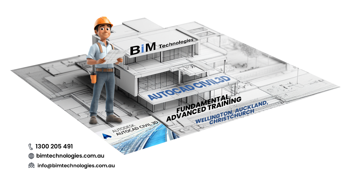
Know something about AutoCAD Civil3D :-
Autodesk Civil 3D is AutoCAD that has been specially customized according to professional needs. It is an industry-recognized software package for civil engineering road and earthwork solutions which can speed up the realization of design concepts. Its 3D dynamic engineering model helps to quickly complete road projects, sites, stormwater/sewerage systems and site planning designs. All surfaces, sections, profiles, annotations, and more are dynamically linked, making it faster and easier to evaluate multiple design alternatives. This will make more informed decisions, and produce up-to-date drawings.
Survey commands are fully integrated into the Civil 3D toolset and user interface. Users can work in a completely consistent environment, from importing field books, least squares adjustments, and editing survey observations, to managing point groups, creating terrain models, and designing parcels and alignments.
Autodesk Civil 3D adds multi-user project support for core elements of Civil 3D models, increasing the efficiency of project teams and reducing the risk of coordination errors when modifications are made during the project lifecycle. Project support in civil 3D leverages the core data management capabilities of Autodesk Vault. This will ensure that the entire project team has access to the data they need to get the work done.
From the colour, line type, and spacing of contour lines to the labels displayed in section or profile bands, a variety of standards can be defined in a style, which is then used throughout the design and drawing generation process.
What are the main features of AutoCAD Civil3D Fundamental and Advanced ?
Here we are giving you some features of AutoCAD and its different courses. So stay here!
[1] Deliver more innovative project designs :
AutoCAD Civil3D Fundamental Training Wellington, Christchurch, Auckland provides better ways to design, analyze, and document civil engineering projects. It enables you to deliver higher-quality transportation, land development, and environmental design projects faster. Specialized tools in the software support the Building Information Modeling (BIM) process, helping to reduce the time it takes to design, analyze, and make changes.
[2] Survey :
Civil 3D fully integrates surveying capabilities so you can complete all tasks in a more consistent environment, including direct import of raw survey data, least squares adjustments, editing survey data, and automatically creating survey drawings and surfaces.
[3] Surfaces and Grading :
With AutoCAD Fundamental Training Christchurch, Wellington, and Auckland, you can create surfaces using traditional survey data such as points and breadlines. Take advantage of large datasets from aerial surveys and digital elevation models with surface simplification tools. Use surfaces as contours or triangles, or create valid elevation and slope analyses.
[4] Plot layout :
The software allows you to automate the process by converting existing AutoCAD entities or generating plots using flexible layout tools. In this way, if a design adjustment or change occurs on one plot, the adjacent plots will automatically reflect the change.
[5] Road modelling :
Road modelling capabilities combine horizontal and vertical geometry with custom cross-sectional components to create parametrically defined, dynamic 3D models of highways and other transportation systems. You can leverage built-in subassemblies, including travel lanes, sidewalks, ditches, and complex lane assemblies, or create your own based on your design criteria.
[6] Pipeline :
Use rules-based tools to lay out domestic and stormwater drainage systems. Graphical or numerical input can be used to cut or connect existing pipe networks or change pipes and structures and perform conflict checks.
[7] Earthwork volume calculation :
With the help of AutoCAD Advanced Training Christchurch, Auckland, you can calculate earthwork quantities between existing and designed surfaces more quickly using composite volume algorithms or average section algorithms. Use Civil 3D to generate earthwork allocation diagrams to analyze the appropriate cut and fill distance, the amount of earth to be moved and the direction of movement, and determine the borrow pit and dump site.
[8] Specialized road and highway design tools :
Specialized transportation design tools can help you design roads and highways more efficiently. Create interactive intersection models that update dynamically. You can focus on optimizing your design, knowing your construction drawings and annotations will always be up to date.
[9] Construction drawings :
Automatically generate construction plans, such as fully annotated cross-sections, longitudinal sections and earthwork construction drawings. Best of all, use external references and data shortcuts to generate sketches for multiple sheets.
[10] Floor plan drawing :
Civil 3D provides a wide variety of features that can help you automatically create cross-section, plan, and profile views. The fully integrated AutoCAD drawing set manager in the Plans Production automatically completes the layout of drawings and drawing lines according to the route, and generates plan and longitudinal drawings based on the layout.
[11] Annotation :
The software’s annotations are derived directly from design objects or through external references and can be automatically updated when the design changes. It also automatically responds to changes in drawing scale and view orientation, so when you change the drawing scale or rotate the drawing in different viewports, all labels update instantly.
[12] Report :
AutoCAD Civil 3D software generates flexible and scalable reports in real-time. Because data comes directly from the model, reports can be easily updated to reflect design changes more quickly.
[13] Data Shortcuts and References :
With external references and data shortcuts, project team members can share model data such as surfaces, alignments, and pipes, and use the same legend of design objects in multiple design tasks.
[14] Design Review :
Today’s engineering design process is more complex than ever, and design reviews often involve team members who are not CAD users but are also important to the project.
[15] Multi-field collaboration :
Civil engineers can import building shells from Autodesk Revit Architecture software into AutoCAD Civil 3D to directly leverage design information provided by architects, such as utility connection points, roof areas, building entrances, and so on.
[16] Geospatial analysis and mapping :
AutoCAD Civil 3D includes geospatial analysis and mapping capabilities to support engineering-based workflows. The software can analyze the spatial relationships between drawing objects. Extract or create new information by superimposing two or more topologies. Create and use buffers to select features within a specified buffer distance of other features.
[17] Sustainable Design :
AutoCAD Civil 3D software can help you improve the sustainability of your civil engineering designs. Engineers can evaluate design options based on reliable site conditions models and design constraints, resulting in more innovative and environmentally friendly designs.
[18] Stormwater Analysis and Simulation :
Design and analyze stormwater flooding systems with integrated simulation tools for collection systems, ponds, and culverts. It can reduce runoff following development while providing sustainable development-compliant stormwater flow and quality reporting. Users can evaluate more design options, including innovative green best management practices, to create more environmentally friendly and aesthetically pleasing designs.
[19] Visualization :
Create stunning visualizations that give stakeholders a head start on projects. Create visualizations directly from your model and get multiple design options to better understand the impact of your design on the community and surrounding environment. Publish your model to the Google Earth™ mapping service to better understand your project in its real-world context.
Now you have a basic idea about the various courses and benefits of AutoCAD. So, if you want to join any of the training, get in touch with BIM TECHNOLOGIES.
In addition, you can also hire Autodesk Inventor 3D modeling services in Wellington, Auckland, and Christchurch.
This software is used for product design, simulation, and visualization. It allows users to create detailed 3D models and assemblies, perform simulations, and generate technical drawings. The software is widely used in industries such as engineering and manufacturing for designing complex products and systems, facilitating collaboration through its integration with other Autodesk products and cloud services for enhanced workflow efficiency.
| Conclusion |
As you can see, taking an AutoCAD course is a great way to gain essential skills in architecture, engineering, and design. With structured learning and accessible funding, you can quickly advance your skills and expand your career opportunities.
Therefore, to know more about our service, get in touch with BIM TECHNOLOGIES!